
Introduction: The Real Friction Hides in the Details
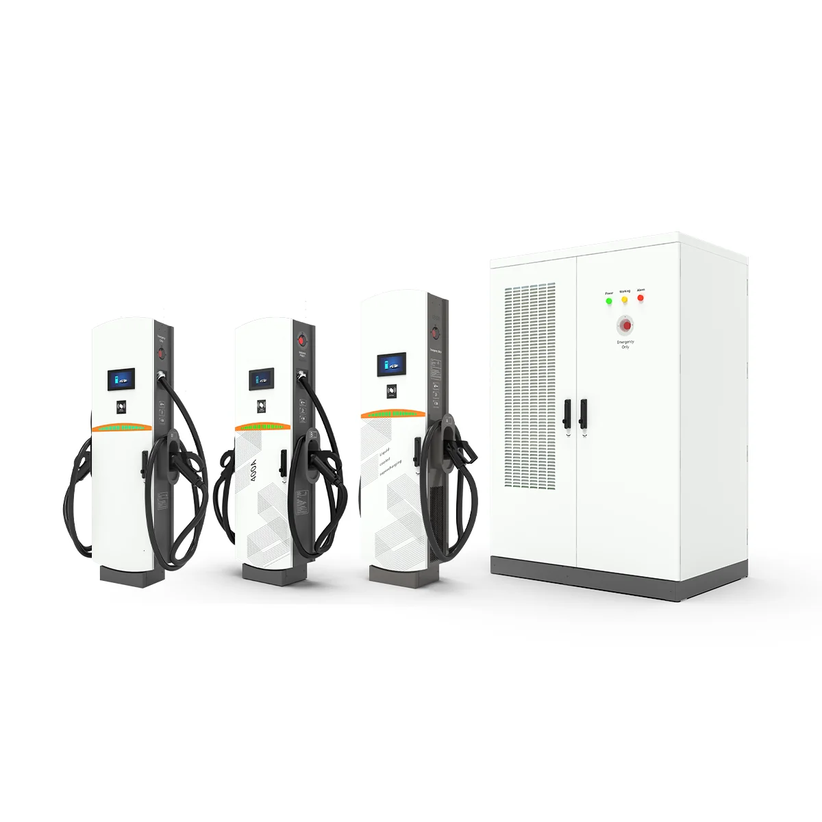
Bold claim: in busy depots and retail car parks, reliability beats raw wattage. 30kw DC fast charger 110 / 40kw DC charger 110 deployments look simple on paper, yet the field says otherwise. Picture a dawn shift where five vans need a 20–40 minute top-up. A site with 96% charger uptime clears the queue; at 85%, drivers sit idle. With a properly sized DC charging station 3600, a 30–40 kW lane can cover 18–22 kWh per stop, if the power converters hold steady and the rectifier modules don’t throttle. But when cooling fans cycle hard or the CAN bus gets noisy, sessions drop or restart (we’ve all seen that). The data tells the story: a 10% hit to throughput doubles perceived wait time—funny how that works, right?
So the question is simple: do you size for nameplate kW, or for sustained, predictable delivery under real loads? And how do you decide when to mix 30 kW and 40 kW units at 110 sites where feeder capacity is tight? Let’s break down what actually goes wrong and how to avoid it—then map a plan that scales with fewer surprises.
What Traditional Rollouts Miss at 110 Sites
Why do legacy setups fall short?
Technical truth first. Traditional installs assume clean AC input, stable ambient temps, and idle network links. Real sites give you harmonic distortion, warm switch rooms, and shaky backhaul. Older layouts use a one-size rectifier stack with little headroom. Under heat, thermal derating cuts 5–15% of output. Then sessions stretch. Add in an isolation transformer that hums at partial load, and you see more ripple on the DC bus. That stresses contactors and triggers residual current protection trips. Look, it’s simpler than you think: power quality plus heat equals silent kW loss.

Control is the second gap. Legacy OCPP 1.6J endpoints often push flat setpoints and lack smart load sharing. Without edge computing nodes at the cabinet, you can’t slice kW by state-of-charge or grid events. The result: one car hogs the lane while others starve. Firmware tries to recover, logs swell, and drivers yank cables. Meanwhile, utility demand charges spike because there’s no peak shaving logic tied to session telemetry—funny how that works, right? A modern plan rights this by coordinating rectifier modules, per-outlet limits, and a temperature-aware cooling loop, so 30 kW and 40 kW lanes both hold steady when it’s hot and busy.
Comparative Outlook: Principles That Make 30 kW and 40 kW Work Together
What’s Next
Forward-looking sites blend power and control, not just bigger nameplate numbers. New control stacks meter energy per minute, not only per session, and use predictive curves from battery handshake to keep current stable near taper. That’s how a 30 kW lane can match a poorly tuned 40 kW lane across a 25–60% SOC window. The practical edge: smaller units with smarter orchestration reduce queue wobble on tight feeders. When you engage experienced partners like EV charging station manufacturers 390 , you can spec coordinated rectifiers, faster fault recovery, and site-level caps that keep demand peaks flat—even with mixed hardware. Add small touches—pre-charge checks, cable temperature sensors, and balanced session starts—and you’ll see drop-offs fall and kWh per hour rise.
Here’s how to compare paths without the buzzwords. First, test sustained output at 35°C ambient with two cars connected; watch for any voltage sag or thermal derating in minute 18. Second, verify load balancing: can the controller re-route 5–8 kW within two seconds when one EV enters taper? Third, check grid impact: THD at the point of common coupling, plus the demand charge model with and without peak shaving. Keep the rest simple—documented recovery from RCD trips, clear logs, and firmware that rolls back cleanly. Wrap these into a site plan that pairs 30 kW lanes for steady churn with a few 40 kW lanes for quick-turn vehicles. You’ll get fewer stalls, smoother driver flow, and a grid bill that behaves (no surprises at month-end).
Advisory close: choose solutions by three metrics—1) sustained kW at heat and partial load, 2) sub-2s dynamic load sharing with SOC-aware setpoints, and 3) verified power quality (THD and inrush) at the service entrance. Nail those, and the rest tends to work itself out—because physics, schedule, and cost finally agree. Learn more with winline technology.